BGR ENERGY SYSTEMS LIMITED

BGR ENERGY


   All Ranges of Deaerators


The Essential Ingredient

Corrosion is the prime enemy to efficient trouble free operation of boilers in utility & industrial power stations. The destructive corrosion in boiler cycles is caused by the presence of gases such as Oxygen and Carbon dioxide and a low pH value.

Today's employment of higher – pressure cycles has resulted in an even greater need to protect expensive components in the feed cycle from corrosion. A power plant would deteriorate rapidly from the ravages of corrosion if Deaeration of feed water was incomplete. The use of BGR Deaeration system guarantees deaerated feed water with an oxygen content not exceeding 0.005 cc per liter (less than 7 parts per billion) and the reduction of Carbon dioxide concentration to zero.


A. Parallel Down Flow Spray – Tray Deaerators

Features

Parallel Down Flow Deaerator Technology offered only by BGR has the following design advantages This Deaerator performs equally well between the extremes of 100% make-up water (below 50 °F) and mostly hot condensate as well as substantial flashing returns

     Handles higher stream flows through the tray stack.

     Requires the lowest temperature differential of any Deaerator to meet operating warranty; typically
       20 °F or less

     Water seal between trays and the spray section eliminates direct impingement of the spray on the
       trays and insures even distribution of the water over the tray stack.

     Higher steam velocities allow use of trays with less open area, which maximizes spilling edge and
       exposes a greater surface of the water to the stripping action of the stream.

     Optimized mixing plus higher steam velocity results in maximum gas removal efficiency.

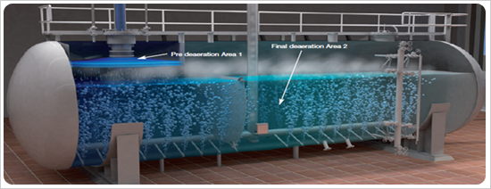
     Only design that guarantees two-stage Deaeration.
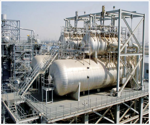
Limitations

     None

Priciple of Operation

     Water enter the preheating compartment and is heated to saturation temperature. Here, the bulk
       of the non-condensable gases are removed before the water enters the trays.

     Heated water passes through the water seal type distributors to the tray section. The water seals
       prevent bypassing of steam into the preheating compartment and insure against non-condensable
       gases entering the tray compartment from the preheating section.

     Water passes downward through the trays to complete final deaeration and then goes to storage.

     Steam enterd at the inlet nozzle and passes through ports in the tray compartment to the space
       above the trays, following with the water through the tray section. This action provides highly
       efficient distribution over the trays, maximizing surface contact between steam and water, and
       prevents damming up of water and possible water hammer. Practically no condensation of steam
       occurs in the tray compartment, since inlet water has been heated to within a few degrees of
       steam temperature in the pre-heater compartment. The entire volume of uncontaminated
       steam is employed in the scrubbing action, thus removing the final traces of oxygen.

     Steam leaves the bottom of the trays, flows outside the trays to the pre-heater compartment
       where it is condensed. Non-condensable gases are discharged to atmosphere.

Deaerating Trays

     One-piece construction, type 430 stainless steel.

     Easily handled by one person.

     The trays are designed so that the pressure shell does not come in contact with the un-deaerated
       water or concentrated non-condensable gases.

     The trays provide excellent performance because they have the highest spilling edge and baffling
       area available in any tray design which allows for maximum water "break-up" and retention time.

Capacities

BGR Parallel Down Flow Deaerators are available at all capacities ranging from 5 TPH to 4000 TPH the following design advantages


B. Counterflow Spray – Tray Deaerators

Advantages of the Counterflow Method

     Cost competitive for large capacity applications

     Highly reliable for attaining specified results
       over a varying load range

     Simplicity and rugged design offers cost savings for many applications, especially where a high
       percentage of condensate returns are introduced

     Good selection for applications with very high percentage of flashing return condensate and for
       higher inlet temperature applications

     Easy access for spray nozzle inspection, even on smaller models

Limitations

     Tray compartment area requirements become unwidely as inlet temperature falls below 60 °F

     Inability to deaerate, condensate from flashing return lines during start-up and re-starts

     requires 40 °F temperature differential to meet operating warranty

Principle of Operation

     Incoming water flows through the spray nozzles and enters the vent-condensing chamber as a thin
       walled, hollow cone spray pattern. Latent heat transfer is instantaneous because of the intimate
       water-to-steam exposure.

     As the water reaches the tray stack, its temperature is within 2 °F of the saturated steam
       temperature, and virtually all dissolved oxygen and free carbon dioxide have been removed.

     Nearly all of the steam has now condensed, permitting the non-condensable gases to be carried
       through the vent by the remaining steam, exiting as a plume.

     The water enters the stack, and immediately reaches saturation (operation) temperature . With the
        water pre-heated, the remainder oh the stack and counterflowing steam are now available to
        scrub and remove final traces of oxygen and carbon dioxide.

     The preheated water flows down over staggered pans in the trays, making its way through pure
        steam flowing in the opposite direction. The water leaving the bottom layer of trays is "stripped" by
        the purest steam entering the Deaerator and flows into storage completely deaerated and heated.

Deaerating Trays

Material is Type 430 Stainless Steel, assembled with Stainless Steel rivets. each tray assembly consists of eight tray channels arranged in two staggered tires of four each.


   Disclaimer | Privacy Policy | Site Map | Feedback | Copyright © 2007 BGR Energy Systems Limited. All rights reserved